The issue here is you are solving “problems” that aren’t the reason audio cables are non linear. It isn’t R, L and C eliminated one at a time. A proper cable needs EVERY variable adjusted in ratios to one another and tertiary effects (skin effect, hall effect, Rs swept resistance, Vp non linearity to name a few) concurrently.
Inductance can never be zero since equal and opposite fields need to be in the same place at the exact same time…true in theory, false in practice. The meissner effect REQUIRES the transition of a magnetic field. Any field requires ENERGY to exist. Where we get energy from is a distortion to that source. When is the last time a superconductors was “free” of energy input?
This Meissner effect happens when electric current loops spontaneously appear on the surface of a material that becomes superconducting in the presence of a magnetic field. These currents create a magnetic field, similar to that of an electromagnet.
If we remove all resistance, we will also find that limiting Vp differential across frequency become very difficult with moderate capacitance. The denominator of the analog Vp differential equation contains R and C. Remove a passive “R” and we are now required to use just a REACTIVE variable, “C”. Not good.
We need to view analog issues in a total 3D relationships and not assume we can remove one or two variables, and not torpedo critical attributes that are directly related to coherence across the audio band.
I know fancy carbon this or that are all the rage, but for the wrong reasons. Passive “R” can be put to good use improving how our analog cables Vp linearity is improved WITHOUT resorting to too much capacitance. Resistance is NOT a problem.
For fiber optics and even Ethernet, we INCREASE the “opposition” to a signal to IMPROVE the signal integrity. Too low a resistance is BAD, as RL (Return Loss reflections) in either medium can only be electronically canceled to a point. What do we do? Use 26 AWG patch and insert optical attenuators to a system to allow better signal to noise properties. Those changes absorb back reflections that lower the signal over the noise. More “R” used right is better.
If you put a zero resistance wire into analog cable, you will NOT like the true measured results. Not even a little bit. The physics we have from time immortal say we can’t eliminate resistance in analog frequencies without increasing Vp non linearity.
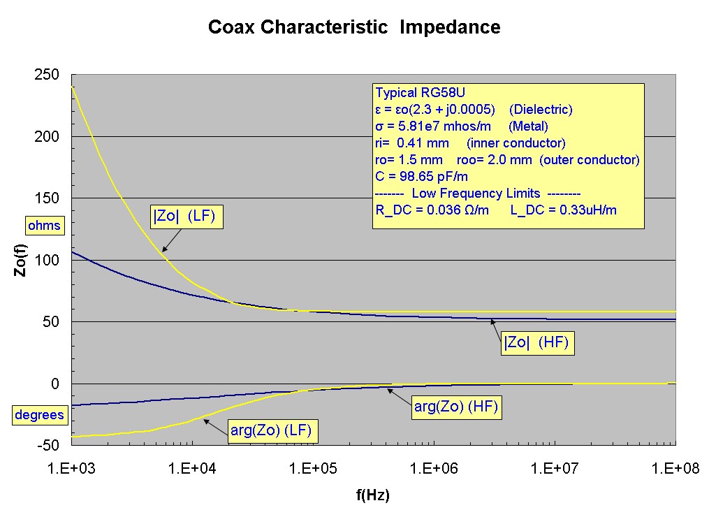
How do we know Vp changes as frequency drops? Here is a chart, Coaxial Cable Characteristic Impedance vs Frequency
I used one that is NOT mine on purpose, the physics don’t do sales and marketing. And, this is not new information but well hidden from analog cable properties.
What do we see in the above chart? We see the IMPEDANCE go UP substantially (upper yellow trace) at lower analog frequencies. At 1KHz the chart shows 250 ohms.This happens because the Vp decreases, and it is in the impedance equation denominator thus as frequency drops, impedance rises. The Vp is defined with R and C of the cable in the low frequency region. We don’t get the nice FLAT 50-ohm curve we see at RF. We never will. Vp goes to ZERO at DC when the signal is there all the time steady state (I don’t count the impulse function when the switch is flicked on) and goes to the RF limiting Vp at RF. We see a transition in the speeds of frequency in the cable as we go from DC to RF. THAT is our big problem in analog cable.
HOW is ANY multi-wire cable (assuming the designer understands what is happening) better? It alters “R” in the Vp differential equation to lower Vp to be more coherent (more the same at all frequencies). If we remove “R”, we are back to square one solving Vp issues with too much reactance. Opps.
Many cable designs increase R (litz wire) and up the capacitance to pretty high levels. Don’t need that as amps get to oscillations with too much capacitive reactance added to the output stage. We have to manage reactance and not just look at resistance by itself.
Each wire, if insulated, is a unique “R” of higher value than one wire of the same aggregate CMA wire area. The total current splits into each wire based on it’s resistance. This is the “R” value in the equation. Capacitance is distributed in parallel so every wire sees the total parallel capacitance. That is the “C” in the equation. Changing C and R alters how a cable measures in the analog time domain.
At RF, we have a different problems. R become a VECTOR (sum of the reactance and resistance). Impedance = SQRT (L/C) at true RF. The wire resistance is the SKIN depth only, not the entire wire cross section. Cable can go into a NIC card and be terminated into the RF “impedance” that is a pure resistor. A good RF cable looks more resistive. The attenuation of RF cables is mainly resistive attenuation and rises with the square root of frequency. If a RF cable deviates from it’s resistive nature, we get increased RL reflections even if the reactive vector is 100-ohms. Part of that is “stored” energy and bounces around. Yep, a perfect 100-ohm cable can have poor RL and an impedance below or above the target impedance can have better RL. Don’t get carried away, to a point this is true.
Vp is flat with frequency at RF. It is the 1/SQRT(e). The dielectric is what defines Vp at RF. Not so in the audio range. We have no group delay problems at RF, well, a tiny bit if the dielectric isn’t RF stable.
Some of these “RF” advantages properties won’t improve analog cable. Nope, they won’t. Can they make analog cable impedance flat with frequency? No. Can they eliminate the group delay (changing Vp) across frequency? No. I don’t see superconductors helping in the audio band.
RF, yes, as attenuation is the square of the frequency. That fact really impacts attenuation. Skin effect at RF says that if we adjust the wire surface area, we reduce attenuation. This is why and RG59 is worse than an RG11 for attenuation. A resistance less surface area will lower attenuation, too. This is why we add SILVER topcoat at RF if we want to tweak attenuation to the absolute best for a given design.
Our ears hear TIME based issues in the analog domain not resistive, which are passive. The better we can get cable non linearity in the time domain, the better the cable at moving data from A to B with low distortion. How good better has to be is always discussed. Analog is a summation of ALL the errors in the system so every option to eliminate the errors is concatenated into the next. Analog error is in total, not a stage.
Making stuff better and better SLOWLY drives the price of that perfection DOWN. No one will reject a better cable (or anything) at the right price. Why would we? Cable can be made better in the analog domain with known engineering, it is just complicated to do it and too low volume to support it. The 80% of the performance at 20% of the price rules. That ratio improves with volume, and understanding.
Best,
Galen
 )
)