Hey - Does anyone know the specs for the hex standoffs for the DS?

I’m trying to order some from Mouser.
-Alan
Hey - Does anyone know the specs for the hex standoffs for the DS?
I’m trying to order some from Mouser.
-Alan
Adriaan (or anybody else who knows some answers), I was just reading your document. Nice work! I have a few questions though:
In regards to the 75 Ohm value of R9 & R10: Has there been any discussion of potential value changes for these which takes into account the performance of one of the newer, better output transformers? Same question in regards to C10. I only ask this because each all three of the better transformers (Lundahl, Jensen, and Edcor) are going to have different roll-off characteristics, as well as inductance. So I can’t help but wonder if the stock low-pass filter values are still optimal for each of the newer output transformers…
Or is C704 the only part which has a value which is likely to be meaningfully impacted inside of the low-pass filter by the substitution of any of the better output transformers since it comes after the transformers?
In the Power tree section, you mention the removal of the “DC filter”. Could you please clarify what you mean by this? The only DC filtering I’m aware of is the power transformer itself, so your meaning is entirely unclear to me.
Are you going to consider adding any information about any of the power supply replacement mods which have been attempted?
Thanks!
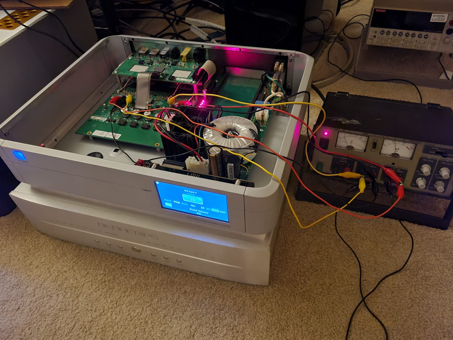
Hello Ted, So as you probably recall I’ve converted the OA to bi-polar +/- 4.x volts now. And Vocm simply = VSS.
Loving how it sounds so far with the MORRE treated inductors and all ![]() Also has tantalum PNM resistors and nude z foils throughout. World premier tonight finally after fixing a couple of oopsies… Piano, everything sounds just incredibly natural, clear and calm. It’s never been so calm playing before. As in, no irritants are coming out. Airy, highly spacious and clear low bass for days.
Also has tantalum PNM resistors and nude z foils throughout. World premier tonight finally after fixing a couple of oopsies… Piano, everything sounds just incredibly natural, clear and calm. It’s never been so calm playing before. As in, no irritants are coming out. Airy, highly spacious and clear low bass for days.
However, the bit re-clocker has about 3.x V DC on its output and the bi-polar powered OA now would prefer that to be about 0… May I ask, what are you doing about that on the TSS?
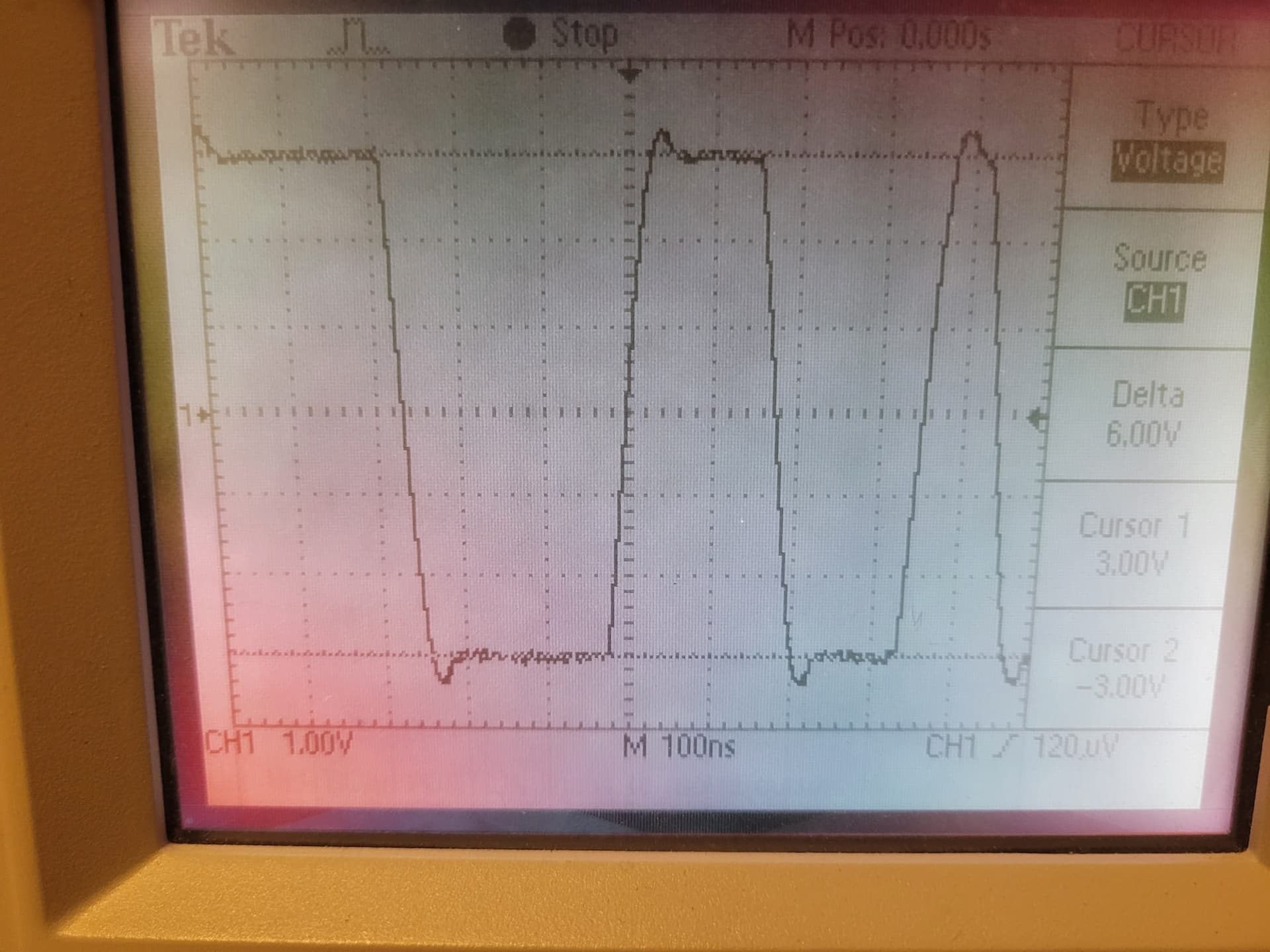
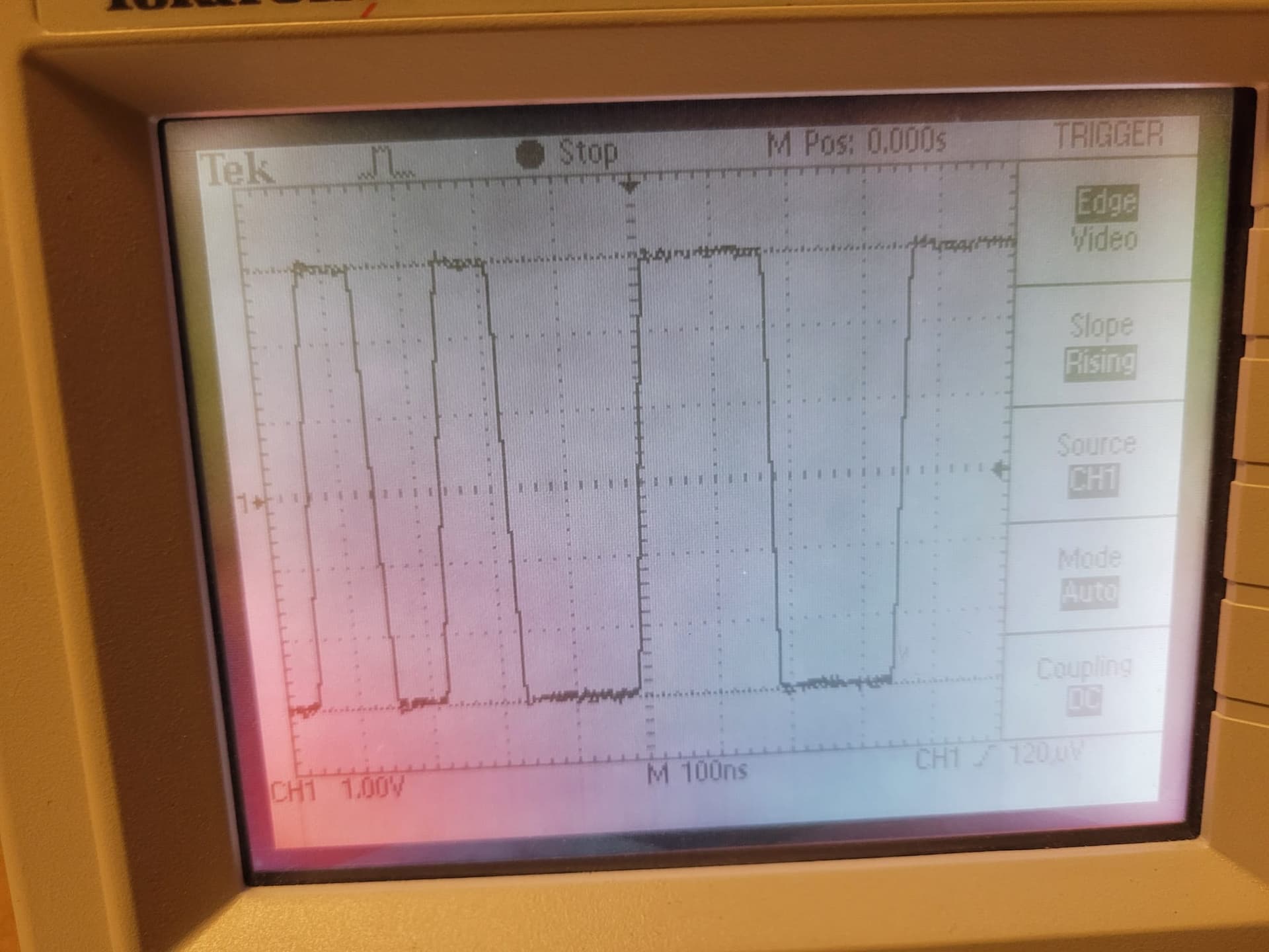
The bits are not yet looking good enough; they have some initial overshoot and undershoot on them leading and falling. This is causing the noise floor to not be as low as we need (yet).
Thanks, T
Bits need solving:
OA section running on lab PSU for now:
On the DS the output of the reclocker is 3.3 to 4.1. On the TSS and DS Mk II it is 1.6 to 2.4V. The DS clock splitter and reclocker can’t operate on 3.3V and if they did a boatload of termination resistors would need to be changed too (and some new ones added as well.)
The overshoot and undershoot are probably the circuit working as designed more than a bug. If the shape of the overshoot and undershoot are constant, it’s probably not a problem. They are more likely going to contribute to THD than noise.
At the speed you are running you can probably cap couple the reclocker to the op-amps. Perhaps 0.1uF like I use elsewhere in the circuit. You would probably want to use a 1k to 10k resistor to center the output of the caps around ground.
One issue I discovered in your document is your choice of the bypass Capacitor for R6. There really is only room in there for a low voltage 50uF electrolytic or perhaps a tantalum cap. And it probably needs to be through-hole as well to be successfully soldered on top of R6.
The 700V 50uF PP cap which is specified as I write this appears to be 52mm long from what I can tell.
Interesting that I didn’t see this overshoot in the previous configuration.
Changes- I’ve moved to OA locations 1 and 3. Also moved it to a new bi-polar OA PSU +/-. There’s also a large DC offset now between the re-clocker out and the OA in pins, separated by a couple resistors.
Even wondering about inductance in the new -VEE lead. Dunno yet but will try and see if I can get anything useful out of LTSpice on that. T
The most straightforward way to implement the Vocm bypass cap is an 0805 pkg SMD tantalum. They go on easy and will stay put. It’s sonically fine for this as well IMO. I used them for awhile, after having started with a Muse electrolytic. Both did the job. T
I have had so many bad experiences with various tantalum caps failing short in vintage equipment over the years that I personally avoid tantalum caps like the plague now. But I imagine that the DS will be far back in the rear-view mirror for most people before the mean time between failure of these caps starts to take its toll.
OTOH I’ve never had an issue with one. Naim audio gear is full of them. All my Naim stuff from the 80’s still working fine BTW ![]() Electrolytics with wet electrolyte have a finite service life usually defined in thousands of hours.
Electrolytics with wet electrolyte have a finite service life usually defined in thousands of hours.
The stock DS board is populated with plenty of tantalum PSU caps.
But, use the one you feel is best of course. T
Naks, Revoxes, and MCI machines often had lots of those “little red devil” tant caps which shorted, and then fried some of the associated circuitry.
Glad to hear that Naim gear has held-up better though.
In principle I avoided tantalum caps like the plague (and still do), but then I was chagrinned to learn that one of my favorite caps, the Panasonic SP-Cap, was a tantalum cap. The difference is an SP Cap is a Special Polymere cap unlike a regular tantalum electrolytic cap. Similar to the difference between hybrid or polymer aluminum caps vs. vanilla aluminum electrolytic caps.
Yes, tantalum shorting was a real issue. It isn’t in the present day though. That unfortunate history will bedevil them though, no matter what. FWIW every PC/notebook in the world is loaded with them. Coming from a 25+ year career of helping the worlds largest PC maker(s) with product development I can vouch to have seen them personally ![]() If they were a reliability problem they would certainly NOT be in there.
If they were a reliability problem they would certainly NOT be in there.
And tantalum for audio doesn’t worry me at all personally. Because I’ve personally listened extensively and compared them in many critical audio applications… signal coupling and DC blocking… bypass… PSU… bias spreader bypass… etc. In fact all my first proto devices used them extensively. They are pretty darn good actually. One reason Naim uses them, which is the main reason I also started out that way as well. Otherwise I may have never done so, but I come from a long Linn/Naim background as well.
OTOH film caps are generally considered to be the caps to use for audio, but I’ve found have a lot of sonic impact/coloration with most of them. Some of the common “industrial” ones can sound very weird, for lack of a better word. Not to mention film have low CV. That said, there are indeed a few that rise to the top. But the rest, not even.
Tantalum C sound is one reason I also decided to give tantalum R a try as well. And those rock with some rather unique qualities as well. Eg natural, non-electronic sound with a black background, generally speaking.
Anyway, long answer again. But just trying to help by providing what I consider a reasonable, easier Vocm alternative to attaching through-hole parts to tiny 0805 pkg leads. At the end of the day YMMV. T
Interesting info @Turbotk . I have read many accounts of Tantalum resistors sounding fantastic. But Tantalum caps have always had a bad rap. I remember a cap shootout performed by Walter Jung many ages ago where he rated tants as dead last sonically, if memory serves.
How do we know that modern tant’s are more reliable though? These didn’t start shorting in-mass quantities until most of this equipment was over 20 years old. But I’ve never seen a computer that old which was still running (not than anyone other than a collector would care).
The Acronym CV isn’t in my vocabulary. Do you mean capacitance as a function of voltage rating?
But you have convinced me that my tant paranoia may be misplaced in this day and age. Are the tants which you suggest actually as tiny as those resistors, or would these be larger bricks hanging off of the top?
The 0805 tants are ~ perfect size to go on the Vocm R. Can install them in minutes, actually.
And man, if tants were unreliable as in early days I’d have them out in a heart beat. So would HP, et al ![]()
CV is just shorthand for energy density really. You can get large C in a small pkg basically. The main advantage. AND they work well at high freq as well, unlike electrolytics. They are used extensively in the industry for that purpose. T
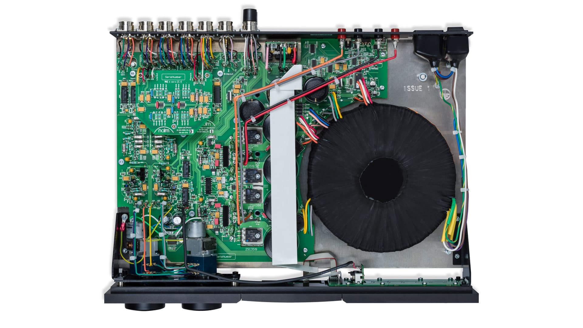
Exhibit A: This is a Naim SuperNait 3 Integrated. I’ve had several Naits over the years, including an old classic Nait 3r until last year. It still sounded great too. Every one of those yellow rectangles and yellow ovals is a tantalum C. I know these Naim circuits like the back of my hand…
" Review: Naim Supernait 3 Super amplifier crushes the competition. Naim Supernait 3 is definitely one of the really good amplifiers. It has everything - except digital inputs."
Seems they don’t sound too bad for audio ;):
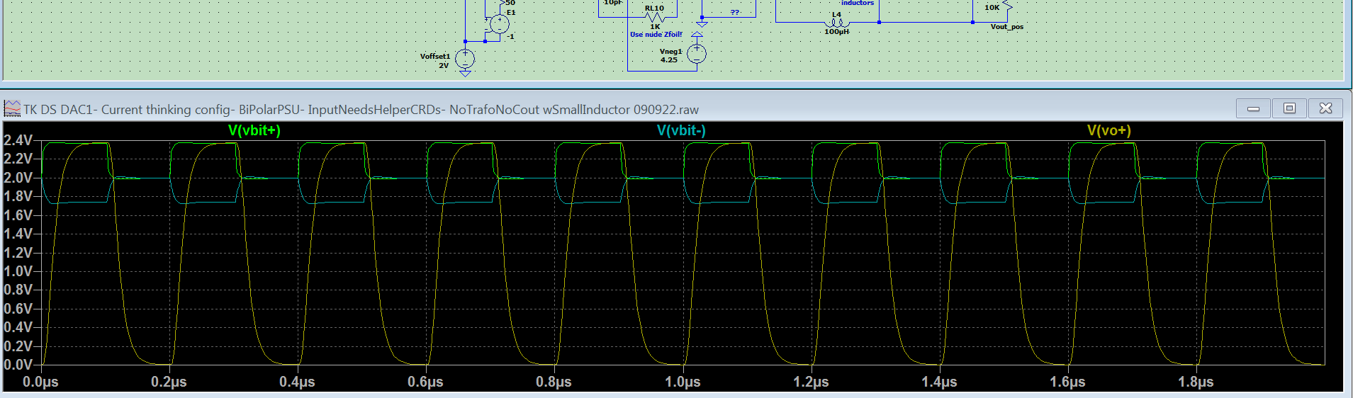
My models aren’t extensive but after several hours simulating I was able to duplicate very well what I see happening currently on the input and the output. Then some light bulbs started glowing a bit thankfully. We may have a good solution for it, as it appears below. We’ll see. T
Vbit+/- are the input bits to the OA buffer. Vo+ is a bit buffer output. I used 2V offset for now rather than the actual ~ 3.5v to more easily just keep it all on the same plot.
And sorry, not to beat a dead horse here. But I recall why I got away from using tantalums in critcal signal coupling application. It wasn’t because of sonics at all; it was because of… (dramatic pause and drum roll):
Leakage! Yes, leakage. Just like an electrolytic. If not for that I might still be using them for signal coupling.
Ever wonder why your classic Naim preamp and amp combo make a nice stout “thump” through the speakers at turn on? Well, now you know ![]()
Naim tried to address it by adding a simple RC time delay output relay on the old 42.5 pre for example, but it’s only moderately useful really as leakage starts large and takes a long time (minutes) to moderate (to a still excessive value for this duty).
Leakage is also a function of C value so one might be tempted to try a smaller than usual value, but it still will leak and thump. Whereas the application actually calls for a (much) larger than usual value to reduce sonic effects and distortion.
Hmm, what to do then… Give up and switch to film, which have ~ no leakage. BUT- now you have to find one that is transparent enough to do the job and stay out of the way sonically… NO small task, trust me… It can take years and $$ in fact.
I’m just full of little trivia bits I guess lol… T
Well it was a good day, made great progress thankfully.
In fact I think this is actually the first time I’ve seen the bit buffer working fully correctly finally (hurray!). All other times there were secondary issues going on.
Also the basic THD+N reading using a full scale 1KHz sine has immediately come back (down) to where it needs to be. Very low, ~ -80dB. Good, good…
A few minor tweaks still to do on the above; and I ordered some parts (of course- seems my obsession lately lol) (QVC would love me). Including a new technology SMD capacitor that looks super interesting for small value applications. Very low voltage coefficient, no piezo effect, ultra high freq operation with ~ flat ESR, etc.
But it should move forward quickly now with getting the super PSU and all into it as well.
Listening to it now, plugged directly into the proto amp and using the built in DS volume control. It’s cabled to the amp via Front Row RCA. Yes sir. We’ve been waiting a long, long time for digital performance like this. Decades, in fact. T
Bit buffer finally working fully. Perseverance pays off:
Just with a cheap pair of headphones it should sound pretty good, give an idea at least. I had the volume up a bit too loud for the phone really:
So @Turbotk , am I understanding you correctly that you’ve now thrown-out all of the op-amp buffers, and that you have replaced them using something along the lines of an emitter follower?
Hello Tarnished. No, these very high speed differential OA have been re-purposed as digital bit buffers. They now buffer amplify the bitstream and that feeds a precision, low noise, no feedback, linear passive LPF. With DSD, the LPF is the actual D/A converter. It needs to be the best it can be.
Also using the higher performing AD8139 rather than the stock low cost AD8132. It has a lower noise spec, wider Vout swing and better performing Vocm if I understand correctly.
With the stock DS the OA do the LPF via a closed loop OA LPF circuit; in the DS case it’s an MFB topology to allow steep freq rolloff.
Notably now also have moved the OA section to a bi-polar OA PSU approach. Ie +/- 5V rather than the stock single ended +7V. This allows no DC on the output, which allows no trafo and no blocking caps. Which is the whole reason for doing so. The stock config is uni-polar PSU which thus requires DC blocking. On the stock DS that DC blocking is done by the differentially driven trafo.
And the DAC sounds good with the lab PSU for that, for now. I’ve used the lab PSU to temporarily power many critical audio projects and know that it gets the job done ok, but can be bettered of course. And the DAC will get much better still with a quiet, high energy, fast transient/very low impedance “open loop” (sort of) super supply (my own terms) for the OA section, coming soon. I’ve already verified while still in uni-polar PSU mode that it does in fact bring a large sonic improvement to the OA section. The actual capacitors used for it make quite a bit of the difference in it as well.
A side note, am asking Audience about possibly treating a cap that I think could be better than their XO-M PP film. If the treatment did work for it, it might then be so good that we don’t really “need” to move to bi-polar PSU. And it would then be the best sounding audio cap I know of. Interesting at least, and we’ll see how that goes meanwhile. I have a bag of 10 I can volunteer for the test treating. T