Hello billg, great to here! I am waiting for my Edcor and MPaudio parts and they should arrive soon. I will get the latest version of SLS-HPULN powersupply with a custom made 60VA 10.7V Premium transformer on a mounting plate. According my measurements, it should all fit inside the DS, but I am quite curious if it works out and how much the DS will improve. 
1 Like
I got the SLS-HPULN and a custom 60VA transformer (very pretty). I think it’ll fit in the dac but the transformer base plate is a tight fit (could be ground down for comfort). But it doesn’t leave any room for additional shielding. So I installed it in an external case and made a good shielded cable. I added a socket on a plate that covers the unused bridge slot. The internal power cable is shielded.
If I was to put the psu inside the case, I’d want keep the mains power away from the digital stuff. I prefer to use clean power from my P10 rather than share it with the digital board.
Good luck with your mods, I’m sure you’ll be well pleased.
2 Likes
Can you share pictures?

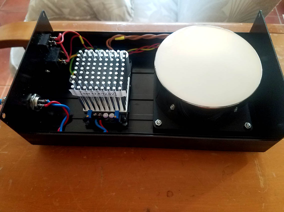
Yep. Very cool.
Hi, new DS DAC owner here in the Austin area, TX  Sorry if this has already been covered, but what is it about the XS4400 transformer (3 pr outputs) that is sonically superior to the stock PCW150/150 (1 pr output)? What makes it sound better? Just trying to understand Thanks, T
1 Like
It’s a higher quality transformer with less roll off on the bottom and the top. It can deal with higher levels before it saturates (tho the DS isn’t driving either of them hard enough for noticeable saturation.) It has tighter quality control on the windings and matches the windings together better by construction.
5 Likes
Thanks Ted. I didn’t see any difference spec’d in the core material or winding material, so was wondering. Does the quadfiler construction make the windings tighter or better? And I assume the extra 2 output pairs are just left unconnected? Thanks, T
No, all windings are used. They are connected on the analog circuit board. Not only quadfiler, but the XS4400 is bigger, longer wire, bigger core, etc. The difference is quite noticable.
3 Likes
The proof is in the listening. I have compare both, one DS Sr. with the stock transformers, and one DS Sr. with the XS4400, and the difference is quite unbelievable. It really sounds like a different DAC of a higher level with the XS4400. It is an across the board improvement in performance.
4 Likes
You are making me crave the new XS4400’s! I love my DSD now I can’t wait for it to improve!
3 Likes
Thanks, and I believe it. Have ordered the XS4400 for my own now  Just wanting to try and understand more of the “how” it’s better. T
1 Like
And just wondering aloud here… I’m too ignorant for my own good, especially about the art of audio transformers (sigh). But am wondering here what happens if the transformer is not smacked by so much energy so far above its native bandwidth. Those sharp, digital bit edges I mean.
I recall seeing mention that the design wanted nice, sharp bits to feed into the transformer. But seems there’s an easy opportunity to start rolling off the digital BW considerably via the array of high speed opamps (switches, in this case) that feed the transformer.
So just wondering please, was this ever actually tried (listened to) in a prototype? Thanks! T
Welcome @Turbotk
The transformer is a part of the passive output filter.
We need the area under the output of each bit from the digital switches to be as close to the same as possible to keep THD down. The problem is that if the edges are too slow, then the area for a 1 after a 1 will be different from a 1 after a -1. The slower slope from the -1 would cut a triangle of area out of the upper left of the 1’s output.
Here’s the original prototype:

I’m not quite sure what suggestion you are making.
1 Like
I should have put something like this in my previous post:

The red trace is a sharp edge (what it really looks like) and the green is a slower edge. Note the difference in area under the green trace in the first half and then in the second half of the long bump.
Here are the calculated differences:

vs

1 Like
A huge difference, yes. And certainly would not be good. Thanks Ted. But I assume that green trace was created by something other than an LPF function built into the high speed diff amps? Can you say what that was?
I’m just wondering what would be like if we had say, a strong 2nd or 3rd order LPF in the opamp, which then is sending out close to a sinusoidal signal to the transformer, rather than a square or triangle wave. Thanks, T
The green was just adding a 500pF cap on the outputs of the opamps. I.e. a sloppy LPF.
I’ve listened to the switches with an integrated LPF and simply having the LPF afterward. There’s not really a big difference (tho I don’t use the integrated LPF in my top end DACs and that sounds a little better to me.) The system is linear so there shouldn’t be a difference. These transformers aren’t overloaded by the magnitude of the signal and their parasitic capacitance isn’t that high so they work fine. I suspect that the differences are the quality of the components available for the two differing LPFs. I should have also reminded you that there’s an RC filter after the digital switches and before the transformer.
1 Like
Ok Ted got it, thank you. And thanks for sharing. The green trace was just a quick experiment in slowing the edge rate I assume.
Todd
Wct, how can I contact you to perform a a transformer mod for me. The forum doesn’t seem to allow me to send anything directly to you.