Hey Amir, nice to meet you! 
I believe I understand your point about resolution vs noise floor, and why applying a 25kHz low-pass filter would change the appearance of the top graph to look more like the bottom one.
I’m curious though which characteristics of the bottom DAC would cause it to produce such a clean-looking trace. The lower quantisation noise afforded by multi-bit sigma-delta conversion? A more aggressive analog output filter than the DS DAC? Both? Something else?
2 Likes
Just worked me through Amir’s entire ‘audio science review’ thread, the final conclusion I draw from this…
@Ted keep up using your incredible talents developing the TSS and new mountain tops instead of spoiling any more energy to a guy hiding behind an anonymous username meanwhile bashing and insulting on his own thread…
he’s not worth it 
Author unknown…seems to fit this thread.
“All truth passes through three stages: First it is ridiculed, second it is violently opposed and third it is accepted as being self-evident”
Thanks for the DS Ted!!!
I love his back story - I’m new to this - I watch Paul’s videos - I might get a sprout- thanks I learned a lot". What’s the end game for the ASR trolls? What motivates the ASR tin eared Troll? It Fascinating…
Typically these days the reconstruction filter is implemented in pieces since a brickwall filter is impossible to implement directly in analog. 1st the PCM (or whatever) is digitally upsampled, this involves a brickwall digital reconstruction/antialiasing filter, but then instead of needing an analog filter that goes from 0dB to -144dB or so in the tiny frequency band from, say 21kHz to 22.05kHz, the digital upsampling filter can be, say, a factor of eight (44.1k → 352.8k) and the analog filter can more gently do it’s thing over the frequency range 21k to 331.8k (352.8k - 21k, about 4 octaves.) A even gentler filter can be used after higher oversampling.
The multibit sigma delta converter does this in addition to converting the higher rate PCM into high rate 5, 6 or 7 bit samples: those sample widths can use much simpler DACs (simple enough that they can be implemented in analog on a digital IC, e.g., a thermometer DAC or a R-2R DAC, etc.) Then the needed analog reconstruction filter can be done pretty simply.
With the DS I could have implemented a much sharper (active) analog filter to make it measure better, but that doesn’t sound as good. Some early SACD players had a switch to lower the analog filter cutoff, but that didn’t sound as good in most systems.
2 Likes
The spikes while there, are not very high in absolute level. The low frequency spikes are a combination of things, for example measuring system noise, like multiples of 60Hz, etc. and show up with the scope input shorted. The DACs 60Hz contribution is lower than average DACs: see JA’s comments about good system layout in the first measurement column. A little is from the transformers distorting the 60Hz trash.
The “hairy” spikes on the left of the ultrasonic frequency bump show up differently depending on the source material and the physical layout of the scope probes, etc. The sigma delta modulation process generates some “birdies” in the rising noise floor (and in the baseband if not done right) I balance the parameters of the SDM to minimize those kind of weirdnesses.
4 Likes
Maybe I’m confused output noise with FPGA noise, but doesn’t the DS DAC gets better with every firmware releases? and every firmware release primary goal is to reduce noise, hence lower noise would sound better than noisier version of DS DAC, and by that logic no noise would sound the best, unfortunately, like absolute zero, no noise is not possible.
The graphs I presented above were all produced with a 22.4 kHz bandwidth/filter, meaning that all the extra components of the signal are in the auditory frequency band, not some noise our ears are unable to hear. This was not previously in my description of the graphs, I have updated my comment with the additional information for clarification.
There are multiple sources of noise in the DS (and any system), the highest one is the one you see on a scope. As I lower various forms of FPGA noise the changes aren’t visible on a scope (and, for example, JA has searched for them) but they are clearly audible.
Here’s my worthless 2 cents as a DS owner (and previously PWD owner).
I’ve never heard of ASR before this so while they may have a folllowing, it’s certainly not mainstream in our hobby. I imagine the readers are not in the market to afford a DS and perhaps is a little like gearheads on a car forum stating why one engine’s performance is better than another, while in reality none of them are using anywhere near the capabilities of either engine. It’s just a pissing match.
In Bascome Kings interviews about the BHK he states in his time measuring amps he found one the measured considerably better than any other (it might have been the Theta since he mentioned a dac company) however it didn’t sound good.
So measurements don’t tell the whole story.
I recently re- listened to some recordings I haven’t heard in quite some time, and with the latest DS OS,
A Basic galvanic isolation device, and turning my TAD cr1’s into a quasi dipole by bouncing my super tweeters off the wall instead of forward (using a mirror and laser to align) i’m Hearing a level of performance and realism I never could have imagined when I began this hobby (or what I hear in most demos).
As an early adopter to the DS I thought it was great compared to the PWD but the level of realism each new OS release brings (except for one or two which I didn’t prefer) the DS brings me more and more of what I hear in live music up close (in people’s living rooms where I can tune my ears to the sound of acoustic instruments in domestic spaces and walk around to hear different perspectives). I don’t need measurements to tell me what sounds like reality and what doesn’t. The BHK 300’s play as big a role as the DS I feel.
I have had experiences hearing other top systems demos that sounded great on certain recordings, but after asking to hear a real world track like a Bill Evans or Rickie lee Jones, the system just sounded flat or worse. On my system those same tracks or other ordinary recording suddenly sound like audiophile tracks with incredible inner detail, and make one feel like they are occupying the same acoustic space that happened during the original recording. I don’t believe a measurement exists yet for that!
3 Likes
Hmm, not near perfect but 1kHz @ -90dBFS filtered (to a lot lower than 20k since my point is simply that the data is there in the noise as the FFT describes):

[Edit]
And here’s the output of a perfect 16 bit DAC with a dithered -90dB 1k sine (using Adobe Audition):
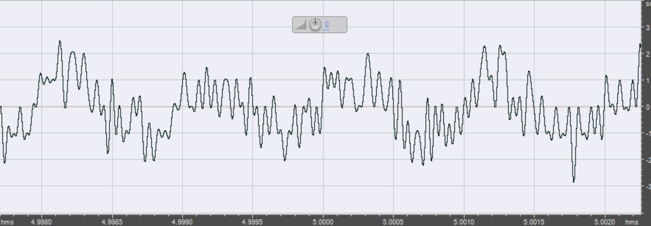
Zoomed in horizontally to show the quantization:

That’s what the DS would look like if it looked like a 16 bit DAC - it’s similar because the DS has noise at a similar level as that that 1 bit TPDF dither in a 16 bit signal - but the 16 bit dac is quantized and you can see that there are only about 5 levels there (each sample is on one of the horizontal lines.) The DS is not quantized at that level (amplitude or time) and the other differences are a tradeoff off: higher noise (which you don’t hear with the DS in a well setup system) for better linearity and (except for the programming in the FPGA) a much simpler implementation.
3 Likes
Sounds like a politician we hear a lot about on Twitter.
4 Likes
Re FPGA (and other noises) When noise is white the ear filters it out pretty easily. Some of the noises I chase out of the FPGA, tho at a lower level than the analog noise, are not very white. Noise that’s correlated to the music is the easiest to hear and it can really color the sound. I haven’t resorted to things like spread spectrum that whitens noise, preferring to instead see if I can avoid generating it in the first place.
3 Likes
Biden or Warren?
4 Likes
Do only I have the impression that we could tell the US political orientation of forum/site members roughly by the character they show online? I could make a list, would be a great experiment (I don’t but it’s somehow scary)
off
2 Likes
I believe I could get a few correct, but most would be a mystery to me.
On the subject of the thread, Thank you Ted for your clarifying posts! I enjoy learning.
1 Like
I specified in the the graphs I referenced that it is a 24 bit signal being used. You conveniently use a -90 dB dithered 16 bit signal to demonstrate your point. Dithering raises the noise floor of the signal to from -96 dB to about -84 dB (I’m not sure what dithering technique you use but this is the standard for dithered 16 bit signals). This raises the noise floor above the signal level, which is why you see such a poor representation of the sine wave of the abobe audition graph. If you do the same with a -90 dB 24 bit signal, you would see a perfect sine wave. Please correct me if I am wrong about this.
This is why it is important to specify the testing conditions as you mentioned earlier. You are comparing 24 bit signals referenced in my post to an unknown (to us anyway since you did not specify) bitrate signal in the pico output graph and a 16 bit dithered signal in the adobe audition graph. This is not an apples to apples comparison and is misleading. If you’d really like to compare with the graphs I have referenced, please use the same signal (-90 db 24 bit) for both the pico and adobe audition outputs. Or if you’d like to keep with the 16 bit, use a level above the dithered noise floor and below the SINAD, say -80 dB. Both of these scenarios should demonstrate the behavior I have been trying to explain.
I agree with you that the data is in there, as I stated above. In my example showing poor performance at -90 dB, I said: “In the first example graph at -90 dB, there is still a 1khz sine wave at -90 dB in the output.” However, having the expected data in output does not necessarily imply good performance. In order for it to have good performance, there should be the expected data and only the expected data in the output. The addition of unexpected signals is what makes your waveform look more like a sawtooth or triangle pattern than a smooth sine wave pattern, which sound different.
I’d like to apply this to a simple analogy. Let’s a take simple RGB pixel consisting of a red led, a green led, and a blue led. If one were to instruct the pixel to produce red, we’d expect only the red led to light up and we would see a red color. However, if one were to instruct the pixel to produce red and we see yellow (red and green), we would think that this is incorrect. I believe you are saying that in the case of the yellow output, because we instructed the pixel to produce red, and red is technically in the output (just use glasses that filter out green light and that would verify that red is indeed in the output), the pixel behaves correctly. My point is that this behavior and line of reasoning is not correct. I’m not arguing wether people can filter out the green with their brain and see only red, I’m saying that outputting yellow is not correct.
Do you listen at 90db? You would be getting hearing damage if you could hear the DS noise floor.
According to the noise floor logic, the difference between 16 and 24 bit audio should only be audible at rock concert volume, and yet most people can hear it in a 60-70db room. Likewise, on the DS I can pretty easily hear the difference between a 16 and 24 bit file in spite of the noise floor, and at 70db listening. If that noise floor is below what anyone will hear in regular listening, and apparent audio quality is high, why does it even matter?
1 Like
Bojo.
1 Like