Cheers Ted. ![]()
I’d be interested in anybody’s extra 3m or Stillpoints supply after they have finished. DM me please. Would only need enough for my one unit.
You were totally right.
I screwed up by excessive shielding.
Today i removed the shielded flat cable (analog-dac board) and the sound opens up.
Thx
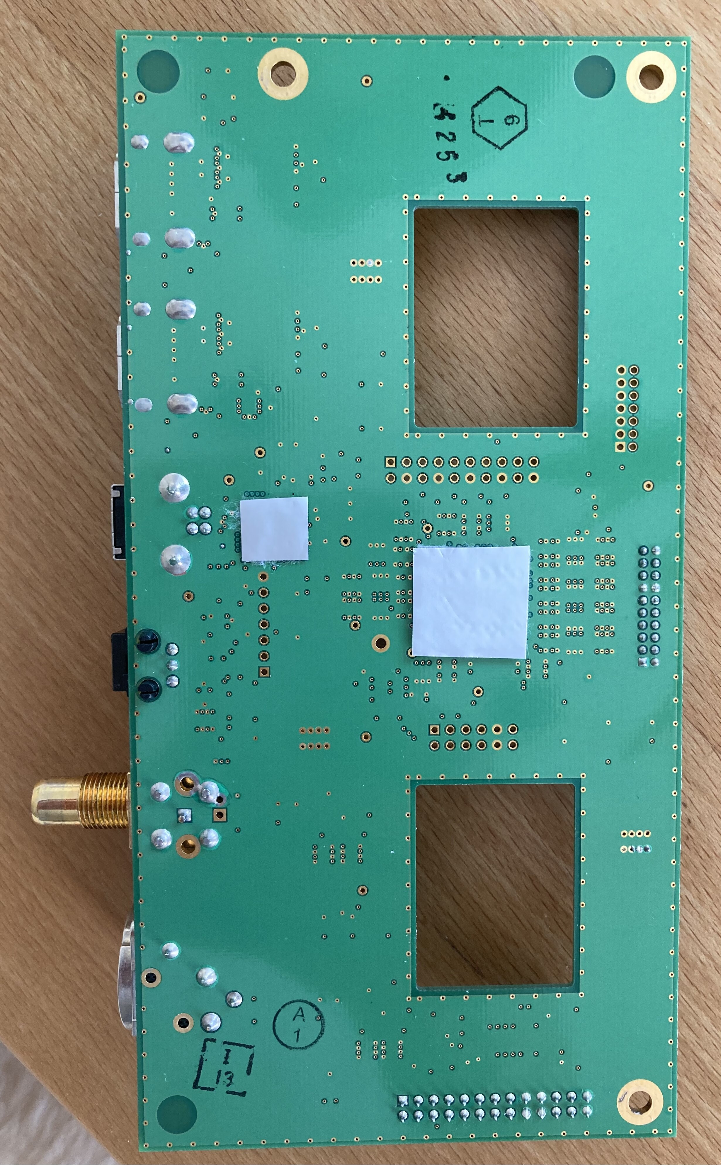
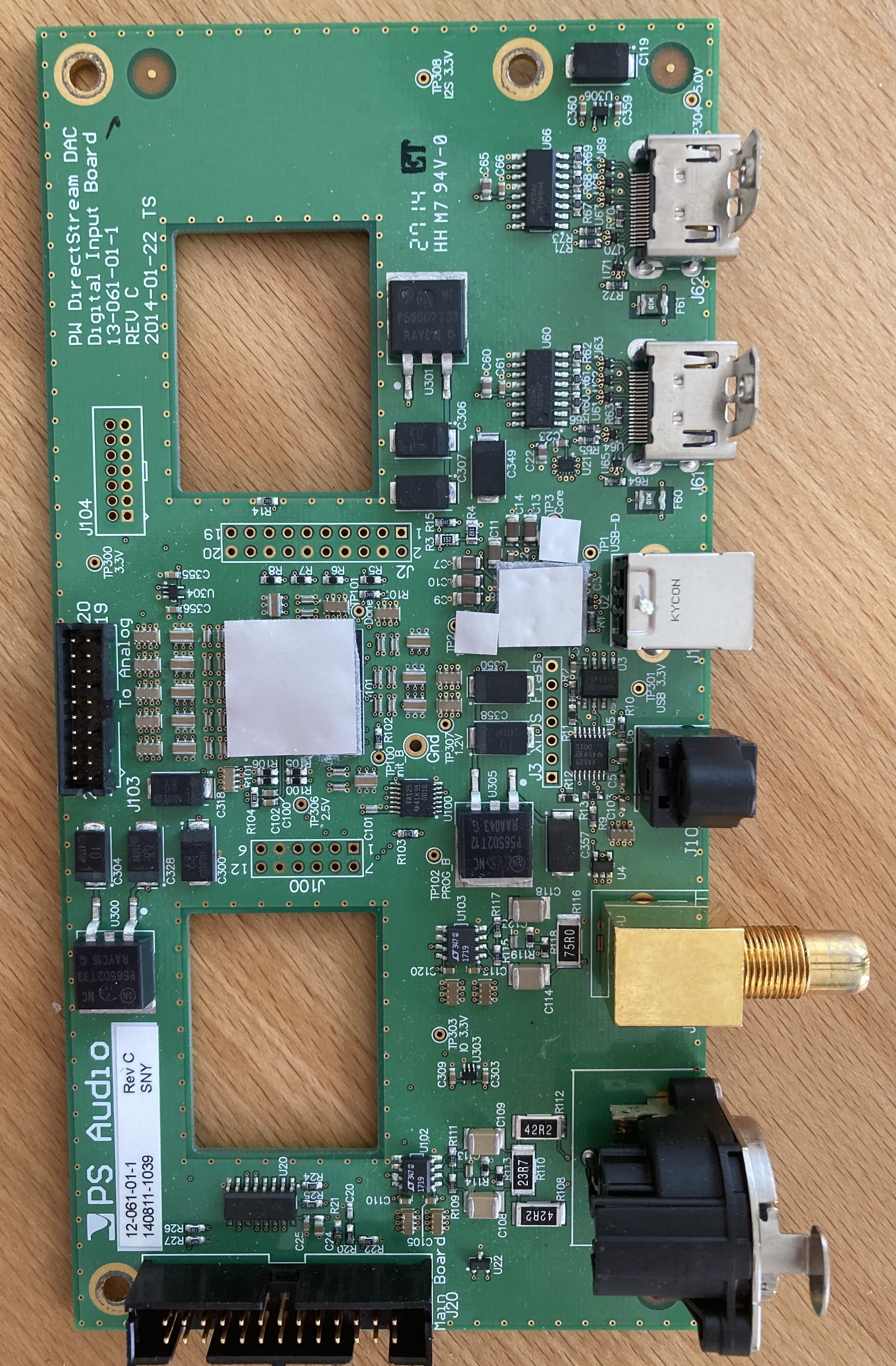
He mentioned on the bottom of Digital card. I put a pie under the noisiest components in a large sqaure. I also gave them roofs.
As I started the worrying about 3M placement, I now try to contribute to clarify after my listening and consideration. I’ll show what I ended up with:
I put a double layer ERS and 3M (just because I had it, don’t think it’s necessary) on the places shown. This sounds better than without.
My recommendation after hours of listening tests:
-Don’t put anything on or around the transformers
-Only cover the dedicated chips, no larger areas (also not the bottom of the digital board)
-you can cover the whole PIC board without problem
Without the top cover, I perceived the DS sounds a bit more transparent, but I wouldn’t sware on it, I had no patience to listen back and forth and certainly used the cover finally.


7 Likes
Good work Sir.
whats the PIC board you refer to,
The Digital input board?
Bit of confusion here with covering up whole of PIC board vs only using on select chips.
Just me being slow ![]()
Thanks.
Stillpoints ERS applied to two spots on Analogue board and for me its a noticable improvement in solidity of soundstage, instrument placement and overall the dac sounds more beefier in its presentation, with better detail.
Nice result.
This what Ive done with mine, underside of digital input board completely covered, as is the back of the display.
Just the Transformer transplant and external PSU to go (have Jkrichards controller board fitted to my DS) then I’m done.

Sorry, with PIC I meant the display board (it was often called so here). It’s the only one where broader coverage with shielding/damping is uncritical from my experience.
Ah.
Thanks.
reconsidering not fully covering the digital board based on your findings?
What differences did you find with just selected chips covered Vs fully covering the digital board?
Feel I’m “fine tuning” the Dac now to my preferred flavour, good to try different options folks have tried.
The differences from too much to less damping/shielding at unfortunate places always were better defined bass, more transparent, better transients. The differences from no shielding/damping to their placement always were more palpable 3D imaging.
In case people need warmth and richness in their setup and might have no very resolving overall situation, they might even prefer a more muddy sound with overdamping or hear no difference. It’s all quite subtle compared to other differences.
And as I said before, ERS is less critical, too much ERS makes smaller differences, too much 3M is more noticeable.
4 Likes
Getting fed up saying thanks to you Jazz,
but one more wont do any harm. ![]()
1 Like
Interesting this big Asix device with U2 ref des did not need coverage of still points or 3M during your investigation . Which board is this? I wonder if @tedsmith can tell us its purpose?
Thanks

I don’t have enough context. That’s not a picture of a part of the digital or analog board and it’s not clear enough for me to read the chip.
If the chip has “Xilinx” or “Spartan” on it it is an FPGA. The caps around it look like that’s what it is.
On the bridge or on the display controller card an FPGA would be used to do mostly simple logic and/or building more clocks, etc. It probably isn’t much of a EMI source.
If it has an “M” that looks like the Marriot hotel logo, then it’s a Microchip PIC (but I think it has too many pins.)
2 Likes
It’s the one on the main Bridge card. You only mentioned the one on the daughter card so far.
1 Like
Then it’s an FPGA, and you probably don’t need to worry about it.
2 Likes
Do chips only or mainly radiate vertically?

7 Likes
hi Ted, thank you for sharing this!
I was in contrary thinking about the “naked” chip pins - doesn’t they considerably propagate RFI? I’m just thinking aloud here ![]()
I thought about that too. My rationale is that radiation comes from large changes in current flow. Most of the lines are high impedance so not much radiation on them. Usually the variations in power flow are larger in the chip than in the bonding wires (things average out by the time you get to the power bonding wires.)
3 Likes
A post was split to a new topic: DS DAC for Sale
2 posts were merged into an existing topic: For Sale: DirectStream DAC Like new with all mods including external Power Supply Awesome Sound