Would it possibly make any benefit if I ran a length of plain copper wire from the screws of my chassii to the safety ground electrode? I have enough spare old cheap speaker cable to do this across the room, where the ground lead exits the wall outside into the 30 meter grounding electrode buried into the field.
Commercial chassis grounding solutions usually include a component box in the middle (an RFI router as they’re called), is it necessary? Surely I can’t get the same performance with just wire, but…
Whaddaya think?
Intuitively I think there could be a “feedback” problem when doing this, since the safety ground electrode is obviously connected to the feed ground in the busbar, so could I actually just induce unwanted ground noise back into the chassii if I were to do this? The RF energy stored in chassii is much lower potential than whatever the fridge (etc) is feeding into the ground and I don’t have diodes to insert between the cable so… Then again the safety ground electrode is certainly the lowest impedance path to ground so is it more likely a sink for RF than a possible backwards source of noise?
Okay so I measured the DAC’s floor noise with a Tascam recorder’s line input from the DAC RCA’s, before and after.
I ran a lead of wire from a chassis screw and connected the other end straight to the bare copper end of the safety ground cable in the busbar.
Here’s the results, upper track is before, lower after:
It sure smoothed some peaks, not a significant reduction in noise floor but it’s something!
When I took line out recordings from the amp’s RCA out now with the amp’s ground screw led to the ground busbar, I noticed in Audacity that WITH this wire, some sharp, very minute leading edges of treble were actually significantly (well that’s exaggerating but yes, quite a bit) reduced, with this “grounding” in place…
I can’t possibly know if this would be a good thing as it’s system dependent and I can’t even be sure if these are all just artifacts of cheap equipment for signal capture and a plethora of factors.
RFI routing could very easily be a series capacitor so HF grunge runs across the capacitor to the field.
LF stuff less so, and it can be a safety issue to connect your mains feed earth to another earth of your own construction (dependent on local mains supply standards.
So my bet is on a series capacitor
I’m not entirely sure if the electrician said if it’s connected to the feed earth, now that I think about it, why would it be? If someone accidentally breaks the feed with a shovel or something, it’d leave the house’s ground floating dangerously so that’s why there’s the “safety ground”, well I guess there’s other reasons for its existence too.
How are the two earths separated inside the breaker panel?
Yes, I’ll go with the capacitor. So I connect wire to chassii screws, lead them all together as one wire and add the capacitor in the middle, then lead that to the safety ground?
Should I actually be using coaxial antenna wire to route RF or will any cabling do?
Big fat earth wires, I reckon, and as you say, screws together then on to capacitor on way to earth connection, but do be careful with chassis and earthing etc.
Will try, wonder how this would compare to the very costly QKORE grounding system. Heh.
I guess I should watch out not to connect anything to the safety earth during a short circuit passing through it! As I understand it, there is almost never anything passing into the safety earth, that’s why I like to think it’s the best tap to route RF into, not to mention it’s the absolute lowest impedance path to earth.
Then again would this arrangement potentially even with the cap create a ground loop since the equipment is grounded to feed ground and here it’s simultaneously led to safety ground?
Then again if there’s essentially never (except possibly during a short) anything going on in the safety ground electrode, does this mean that it won’t create any loops since there’s nothing to loop back? (So it’d be just a sink?)
By intuition I think I might be right but please correct if not.
CAN this really be as simple as routing all component screws together, through a cap and into safety ground electrode?
There are those multikilodollar grounding solutions available and yes, people are surprised by the difference it makes to both ground all components AND route chassis RF away…
The solution you recommend, John, is probably around fifty bucks. @joma0711
Care to recommend exactly the type of capacitor for the experiment?
I’m wondering if, for RF grounding, I should use silver plated wire, well, due to RF skin depth…
Oh, I don’t know if circuits are needed between the chassii here in particular, mainly I’m seeking to drain RF energy away from them since that’s where it’s stored and radiates onto internal circuits.
There are proprietary technologies for doing this either by connecting to an “RF router” box by RCA, USB, ethernet, any input really, OR connecting by wire with spades from the chassis screws.
Here I’m really hoping a meaningful result is possible without proprietary boxes involved…
(But yes, good suggestion for those who do have ground loop problems)
If your equipment has three-prong plugs, there is a super-high probability the equipment chassis is connected to this third prong (ground). If you feel this ground is not good enough, then ensure your home electrical board is grounded with a long stake into the earth outside your home.
I just sold my home and had an inspection done to head-off any issues with a buyer. The inspector found I did not have a real ground bar hammered down into the ground so I added one. You should get a real electrician to add this to your home or at least come out and inspect the bonding. Sometimes, the panel is bonded to a water pipe which is supposed to do the same, however my inspector (and then the electrician) said “not good”. If your home is old and may have had plumbing re-configured or repaired, sometimes the bonding can get broken or attached to a pipe that does not go out the home via a solid connection anymore.
If your equipment only had a two-prong electrical plug, then the unit is designed as “double insulation”.
Personally, I would never run a wire from a chassis to anywhere other than another piece of stereo equipment as you may, by definition, creating a ground loop. This may or may not induce or reduce hum/noise. Before I started screwing around, I would make sure the fundementals of grounding are in place in your home. Then… move to the next item.
I had a problem with hum in an apartment building I lived in Center City Philly… so no hope of fixing the grounding system there. So I purchased a Tice Power Block and it eliminated all hum.
My grounding is good, there’s a thick 20 meter ground electrode buried into the field. Nothing really goes there I assume, it’s a safety ground that prevents accidents if the feed’s ground is damaged, etc. I am assuming all the ground mainly goes into the feed’s ground, though not certain.
This is quite rather a thread about a somewhat uncommon tweak for maintaining a clean RF-free (and other junk-free) ground for the audio system.
Though the RF I guess goes into both directions, onto chassii from the outlet and then back into outlet and onto all other chassii, my understanding though is that metal chassii are where RF energy “likes to live” so I guess by routing it away from chassii would also route it away from the mains that way?
I am not sure.
Though of course it can be additionally routed away from the mains by leading it to a “passive ground” straight from the sockets.
Then, check to see if your main board allows for isolation grounding. IG is common in commercial buildings but not residential. If you board allows for it, then install dedicated IG cable and sockets. That helps a ton.
Even if your electrical system does not allow for it, I would still install a dedicated 20 amp circuit and run a dedicated ground back (4-wire cable) to the panel, and then plug all equipment into that one circuit. I did this in my last home with a dedicated circuit, dedicated ground to each area with electronics. Stereo, home theater, computer room, office desk.
I treat what I did above as “basics” before I screw around with other audiophile tweaks. It may be entertaining to stick a coat hanger in your ear or whatever, but again, the basics first.
It helps isolate noise created by other things attached to the board, such as transformers or appliances. Hospitals install IGs all over the place to isolate sensitive monitoring equipment. You can recognize an IG outlet by the little triangle on the plate/socket. They are usually orange but I’ve seen then in other colors.
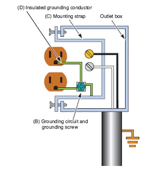
The Article 406.3(D) of the 2014 edition of the NEC requires orange triangle identification on the Isolated Ground Receptacles.
The requirement for Isolated Ground Receptacles arises from the need to efficiently and economically protect sensitive electronics which a conventional receptacle may not able to provide.
A conventional receptacle is grounded to the building grounding system at the receptacle. When mounted in the box, the receptacle’s grounding contacts are connected to the box, fittings, conduit and all other building ground system components which can act as a large antenna for EMI and RFI (electronic) noise.[1]
Isolated ground device is different in a way it easily protect sensitive electronics or equipment from damage without the expense of using power conditioners. Grounding contacts are bonded directly to the service entrance grounding system. In the illustration the insulating barrier (A) isolates the grounding contacts (B) from the mounting strap (C). The insulated grounding conductor (D) is bonded to the service entrance grounding system, resulting in the protection of equipment that
draws power from the isolated ground device.[1]
I don’t quite understand what different brands are doing.
If you connect all chassis via a cable you create different ground loops.
All ground connections of the power chords are connected (on the mains site) and these are mostly connected to the chassis.
The same applies if you also connect all signal ground connections.
Paul isn’t so sure what’s inside the proprietary boxes… Well if we consider for example the Russ Andrews RF router, it’s not so difficult to imagine how to attain lowest possible RF impedance, surely not very complex, many ways to do that. The thing that I’m wondering about… Wouldn’t we need very specialized wire to connect to it, to keep that low RF impedance all the way to ground? Silver plated at the very least?