Here is the ICONOCLAST Jacket operation. They are all the same except that the TEXTILE color under the FEP is our “jacket” color. I use clear FEP as it is still UV proof, and the COLOR stays 100% the same as it is easier to die TEXTILE consistently than to dye FEP extrudeate in thin walls.
First picture is raw let-off bulk cable with the textile braid.
This is a high speed BINDER head applying the spacer FEP thread around the “conductor” for an IC cable. It can be a 1x1 or a 1x4, the same “spacer conductor” goes into the RCA and XLR, no changes except the “core”
Exactly what I was looking for. I dont think many realize how specialized this equipment is and how fussy it is to keep dialed in and still run at high speed.
Thanks for the photos.
We have either the BLUE series I or II in SPTPC or OFE copper color code. The color is the price class and material. The SPTPC has a different patina than the OFE so it is easy to differentiate and we can consolidate colors and costs this way. The reel below holds OFE extrudate polarity
Our oldest customer makes spun paper products. You would recognize paper bag handles but they make hundreds of similar products all by an ancient process brought up to modern production standards by modern electronics but the core of the machinery is still over 100 years old. One of their more interesting products is the filler for lace trim on high end wood coffins.
Those weaving machines go all the way back to the textile industry probably before electricity was nationwide. We did some work on weaving machines like that for a sock manufacturer. To see them run is mesmerizing and they make music of their own when running in full song.
A FEP inner jacket is applied over the core after it is cabled.
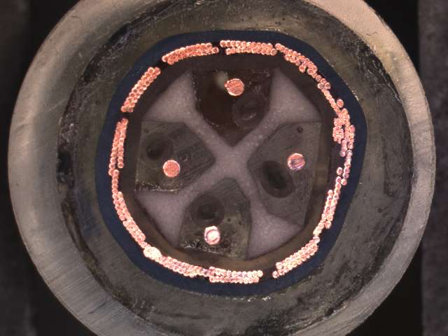
We can make the series I or II, here is the series II XLR with the sixteen 30 AWG wires, four per chamber.
I dont remember the manufacturer. It seems like there were 24 needles, 24 spools of thread, and a mechanical skip mechanism that was changed out or adjusted to change the pattern in the weave. The machines were completely mechanical with only an electric motor to run them. They had a flywheel that you would run by hand to get them moving and then engage the clutch to make them run continuously. The owner of the business was 77 years old and it was the only job he ever had. Those machines were his children. It was fun making parts for the machines that were no longer available.
That is so cool. As I said most peeps dont have any idea how something like that is made. A good friend used to say that everything is simple once you get done. It’s the getting done that is hard. Also high speed processes make high speed wrecks when things go haywire.
Thanks again for posting!
After that we build small air tubes out of heat shrink. We are just before silver solder here. All that work wants to FALL APART if you aren’t real careful! This is a male header.
Now we have a silver soldered male assembly, ready for the connector body.
We add the inner crimp and front header to the male or female terminal body. This is a FEMALE pin header.